How to Get the Perfect Line Width Settings in 3D Printing
There has been quite a bit of confusion among 3D printer users when talking about line width, and why you might want to adjust it for your models. I’ll attempt to simplify things, so you can get a clear understanding of the setting.
People wonder, how do I get the perfect line or extrusion width settings when 3D printing?
Many slicers default the line width to between 100% and 120% of the nozzle diameter. Increasing line width is great for increasing part strength, while decreasing line width can improve printing times, as well as print quality. The minimum and maximum is around 60% and 200% of the nozzle diameter.
This is a brief answer that gets you going in the right direction. Learning more about important 3D printer settings not only makes you better at the craft but also helps you understand the whole phenomenon in general.
Continue reading for valuable information and more details that discuss line width settings.
What is the Line Width Setting in 3D Printing?
The line width setting in 3D printing is simply how wide your nozzle extrudes each line of filament. With a 0.4mm nozzle, it’s possible to have a line width of 0.3mm or even 0.8mm. A smaller line width can improve quality, while a larger line width can improve part strength.
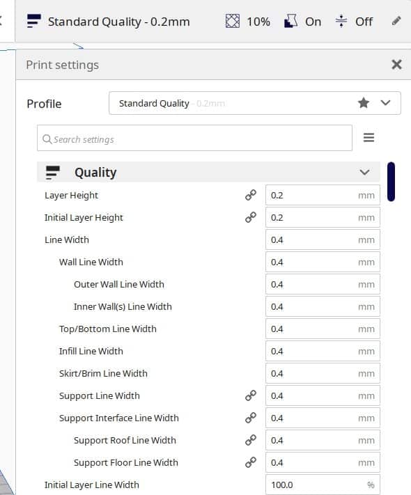
When you look at your line width setting within Cura, or your chosen slicer, you’ll usually find it under the quality settings.
Depending on how you adjust your line width, you can get different results out of your models.
The line width is more of a general setting which also has many settings within such as:
- Wall Line Width – the width of a single wall line
- Top/Bottom Line Width – the line width of both the top and bottom layers
- Infill Line Width – the line width of all your infill
- Skirt/Brim Line Width – the width of your skirt and brim lines
- Support Line Width – the line width of your support structures
- Support Interface Line Width – the width of a support interface line
- Initial Layer Line Width – the width of your first layer
All of these should adjust automatically when you change the main line width setting, though you can adjust the individual settings as you desire.
Generally, your slicer either has a default line width anywhere from 100% of your nozzle diameter (Cura) to around 120% (Prusa Slicer), both of which work well for your prints. There seems to benefits to different line width values, which we’ll explore in this article.
It’s fairly simple to understand how the line width settings work, though it can be confusing as to what it actually helps with.
What Does the Line Width Setting Help With?
The line width setting can help with:
- Print quality and dimensional accuracy
- Strengthening up your 3D printed parts
- Improving your first layer adhesion
I wrote an article about How to Get the Best Dimensional Accuracy in Your 3D Prints.
The line width setting has effects on quite a few factors, the main ones being making your final prints look better aesthetically, and actually making your parts stronger. The right adjustments can improve your printing successes, especially if parts are weak in some areas.
For example, if you find that your prints have poor first layer adhesion and aren’t sticking to the bed well, you can increase your Initial Layer Line Width so there is more of a foundation and extrusion for those crucial first layers.
Check out more about How to Get the Perfect First Layer on Your 3D Prints.
Many people have improved their printing successes by adjust these settings.
In terms of strength, you can look towards the Wall Line Width and the Infill Line Width. Increasing the width of these two settings can definitely improve your overall part strength since it will make the important sections thicker.
We can also find help within the line width settings when wanting to produce more precise 3D prints.
With experimentation within the 3D printing community, a lower layer line width has significantly improved part quality.
How Does Line Width Affect Printing Quality, Speed & Strength?
In this highly descriptive video, CNC Kitchen explains how increasing extrusion lends strength to your parts. Take a look at it below.
When your 3D printer determines how thick it’s going to extrude lines, a number of factors such as strength, quality, and speed are affected. Let’s look into how each factor reacts to changes in line width settings.
What is the Affect of Line Width on Print Strength?
If you increase the line width, you’ll get thicker extrusions with improved layer bonding. This will make your part very efficient in doing what it normally does, and all at the same time as thin or normal extrusions.
For instance, if you go for 200% line width as described in the video above, you’ll get high strength mechanical parts. However, this is not going to be without compromising the quality.
I’m sure you can picture the other side of this equation where a thinner line width is likely to make your 3D printed parts weaker.
There is going to be less material and a lower thickness, so under a certain amount of pressure, you may find parts breaking if you significantly reduce your line width.
What is the Affect of Line Width on Print Quality?
On the contrary, if you decrease your line width in accordance with your nozzle diameter, that can turn out beneficial too. A thin extrusion width is going to print objects with more accuracy and can lead to less print failures.
Cura mentions that decreasing your line width can help out with getting more precise prints, as well as smoother and higher quality parts. Some people have actually tried printing with narrow line widths and seen worse results, so there are other factors that come into effect.
Therefore, it entirely depends on your personal preference and the type of result you’re trying to get with your models.
You definitely want to try different line widths so you can do your own testing and really see how the print quality turns out with various line widths.
What is the Affect of Line Width on Print Speed?
Print speed is definitely affected by what line width you choose to set in your slicer. This comes down to flow rates through your nozzle, where a thicker line width means you are extruding more material, and a thinner line width means you aren’t extruding as much material.
If you are looking for a strong, mechanical part quickly, balancing out your line width is essential.
You may want to look towards other settings if speed is your main desire, since line width doesn’t have the most significant impact on printing speeds, though they do contribute.
What you can do is increase just the Wall Line Width for better strength, while having a lower line width for the infill to improve on speed, since the walls contribute the most to part strength.
Do keep in mind that your infill pattern can have a significant impact on timing when adjusting your line width settings.
How Do I Get the Perfect Line Width Setting?
Getting the perfect line width setting is going to come down to what performance factors are important to you.
Take the following for example:
- If you want the strongest, functional 3D printed part possible, then having a larger line width in the 150-200% range can work really well for you.
- If you want to 3D print really quickly and don’t mind having lower strength, the 60-100% range is going to be your best choice.
- If you want some great print quality, lower line widths have worked for many people, also being in that 60-100% range.
Generally, the perfect line width setting for most people is going to be the same as their nozzle diameter, or around 120% of it.
These settings provide a great balance between speed, strength, quality, and adhesion to your 3D prints, without needing to sacrifice some of the key performance factors.
Many people love going for the line width that is 120% of their nozzle diameter. This translates to a layer or extrusion width of 0.48mm for a standard 0.4mm nozzle.
People have had great success with this line width setting. It provides a nice mix of strength and adhesion without sacrificing print quality.
I’ve heard other people swear by an extrusion width of 110%. The Slic3r software has a calculation which sets extrusion width to 1.125 * nozzle width as a default, and users have said how amazing their top surfaces were.
If you’re looking for a more functional part where mechanical strength is a must, try pumping up the line width to 200%.
Not only will this allow you to get great strength in your models, but you’ll find that the printing time will shorten as well. The reason this happens is because the infill gets thicker and fewer lines are needed to be extruded.
On the other hand, if the initial line gets way too thick, it starts crossing over the next set of layers, thereby forming raises and bumps in your print. This could even lead to your nozzle bumping into your print if its bad enough.
Nobody wants that.
What’s ideal here is that the initial line width should be just enough so only that amount of filament gets extruded out which gives us a smooth line and doesn’t have any bumps or pits in it.
For a 0.4 mm nozzle, it would be a great idea to shoot for a line width of between 0.35-0.39mm. This is because those values are just under the width of the extruder nozzle and are more uncomplicated to extrude.
By default, Cura also suggests, “slightly reducing this value could produce better prints.” This is true in many cases and can be beneficial for the quality of your prints.
Another trick that people have found effective is by adding together the nozzle diameter and the layer height. The result would be their ideal line width value.
For instance, a nozzle diameter of 0.4 mm and a layer height of 0.2 mm would mean that you should go with 0.6 mm of line width.
This might not work for everyone, but it has worked for many. In the end, I suggest playing around with this setting until you find that sweet spot.
A member of RepRap’s community says that he uses a fixed value of 0.5 mm for his line width setting regardless of his nozzle diameter and that gives him satisfactory results.
Therefore, there’s not a single “perfect” setting that works for everyone. People have tried and tested and the majority of them agree that 120% of line width bodes well for most print jobs.
That said, you’re always free to experiment by decreasing or increasing that value and see how it turns out.
List of Extrusion Width Ranges for Different Nozzle Sizes
The following is a list of extrusion width ranges for different sized nozzles.
Note: As for the minimum extrusion width, some people have even gone lower and made successful prints. This, however, at the expense of lower strength because of thinner extrusions.
| Nozzle Diameter | Minimum Extrusion Width | Maximum Extrusion Width |
|---|---|---|
| 0.1mm | 0.06mm | 0.2mm |
| 0.2mm | 0.12mm | 0.4mm |
| 0.3mm | 0.18mm | 0.6mm |
| 0.4mm | 0.24mm | 0.8mm |
| 0.5mm | 0.3mm | 1mm |
| 0.6mm | 0.36mm | 1.2mm |
| 0.7mm | 0.42mm | 1.4mm |
| 0.8mm | 0.48mm | 1.6mm |
| 0.9mm | 0.54mm | 1.8mm |
| 1mm | 0.6mm | 2mm |
How Do You Calibrate Extrusion Width?
Appropriate settings and optimizations are half of what makes 3D prints successful, and extruder width calibration is no exception.
This is a crucial part of getting your print jobs right since a badly calibrated extruder gives rise to a number of 3D printing problems such as under-extrusion and over-extrusion.
This is why you need to attend to this matter and sort your extruder width out to utilize your 3D printer’s full potential.
You do this by first checking out your E-step calibration and confirming that it’s good to work with.
For those of you who are new to this, E-steps are the number of steps that the stepper motor takes for extruding 1 mm of filament.
You can check your E-step efficiency by printing 100 mm of filament and then measuring the length of what’s extruded. If you don’t get a precise answer, it’s time to get to calibrating.
Once you’ve got all that down, the next step is venturing on to your extrusion width. This isn’t very complicated, but you will be needing a Digital Caliper.
Begin by calculating your filament’s average width by measuring it at 4-5 distinct points. If you find the result different than what’s normally known as 1.75mm, enter the measured value in your slicer.
Then, you’ll have to download a model that’s specifically used for calibration. It’s called the “Calibration Cube” which you can get it from Thingiverse.
The print should have no infill and no top or bottom layer. Moreover, set the parameter to only 2 walls. When you’re done with printing, measure the average thickness again with your caliper.
You can use this formula now to calibrate your extrusion width.
desired thickness/measured thickness) x extrusion multiplier = new extrusion multiplier
You can easily repeat the process until you fully calibrate your extruder. You can refer to this article for more detail on this calibration method for your extrusion width.
Is the “line width” dependent on the brand/type of filament? If so, should this value be calibrated for each filament and manufacturer?
Line width is more general so it doesn’t depend on the brand or type of filament. Mainly on the 3D model itself
i’m not sure that the printer will erogate more flow if the line width is incremented ..from my experience the walls are simply more distant from each others but i dont see more extrusion …
Interesting point sounds reasonable, yeah I’m not sure 100% on this. Haven’t done testing on that point specifically